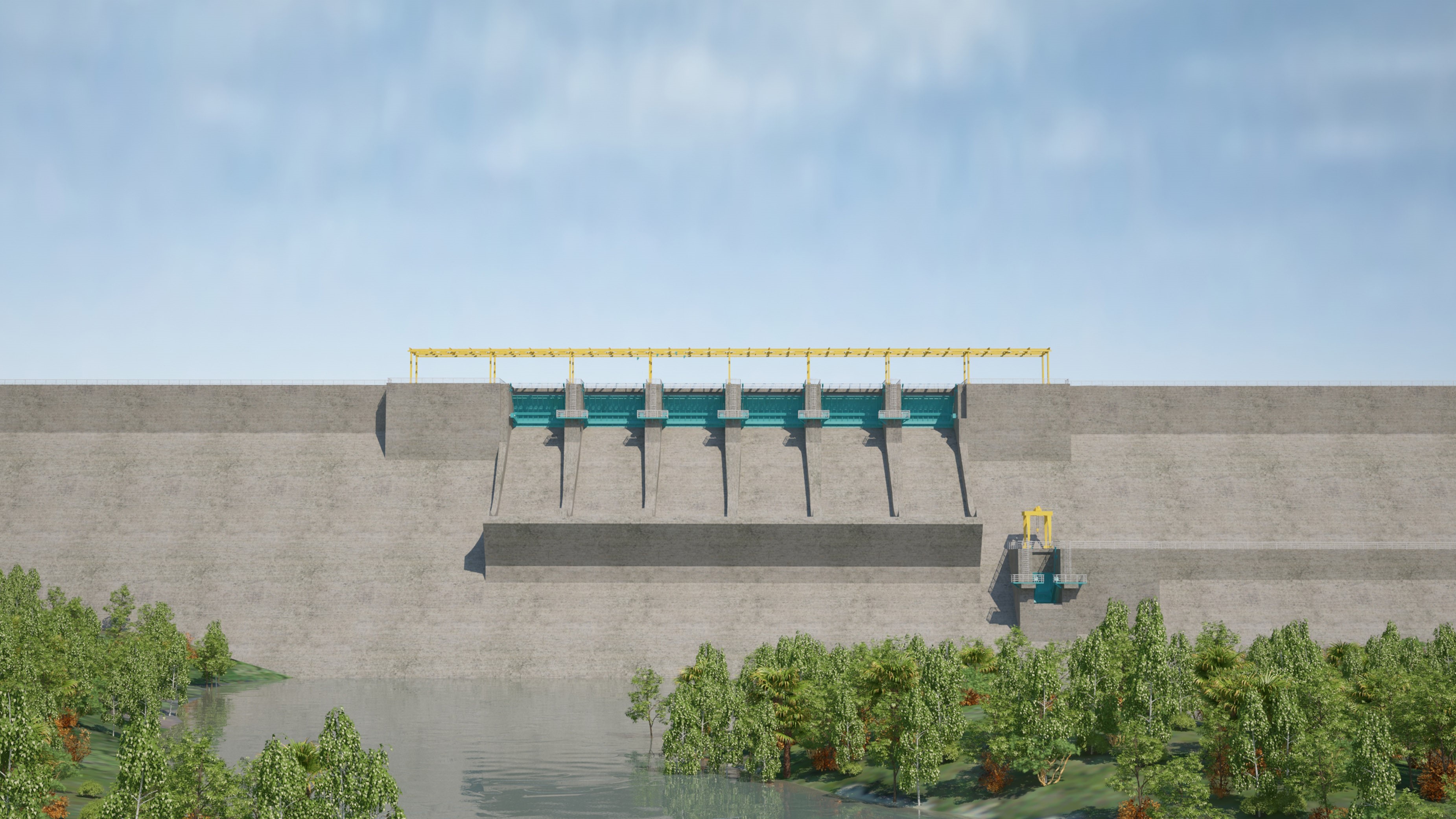
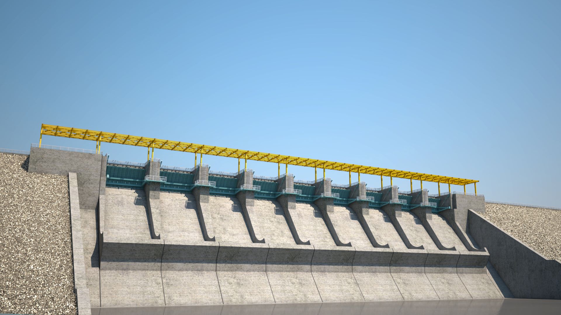
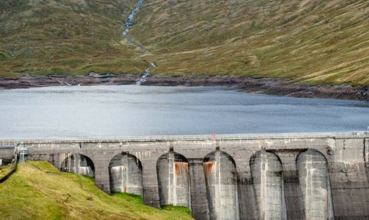
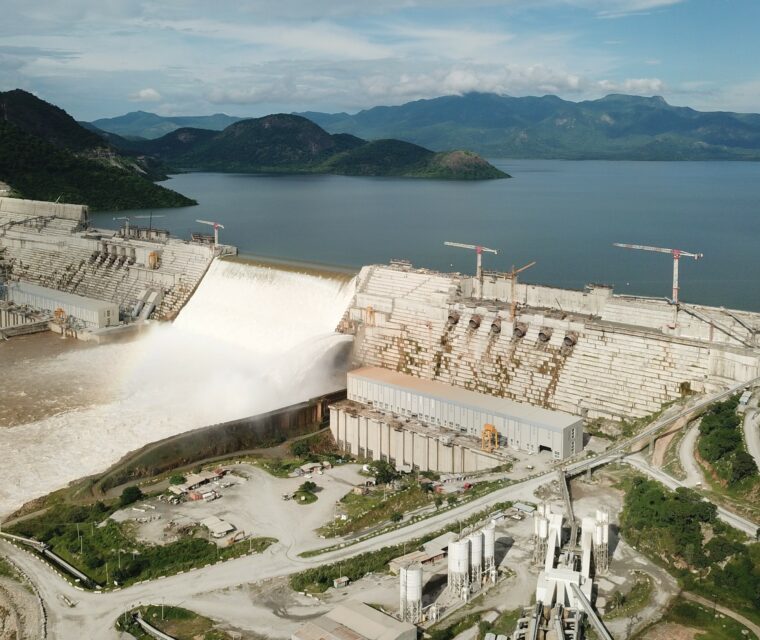
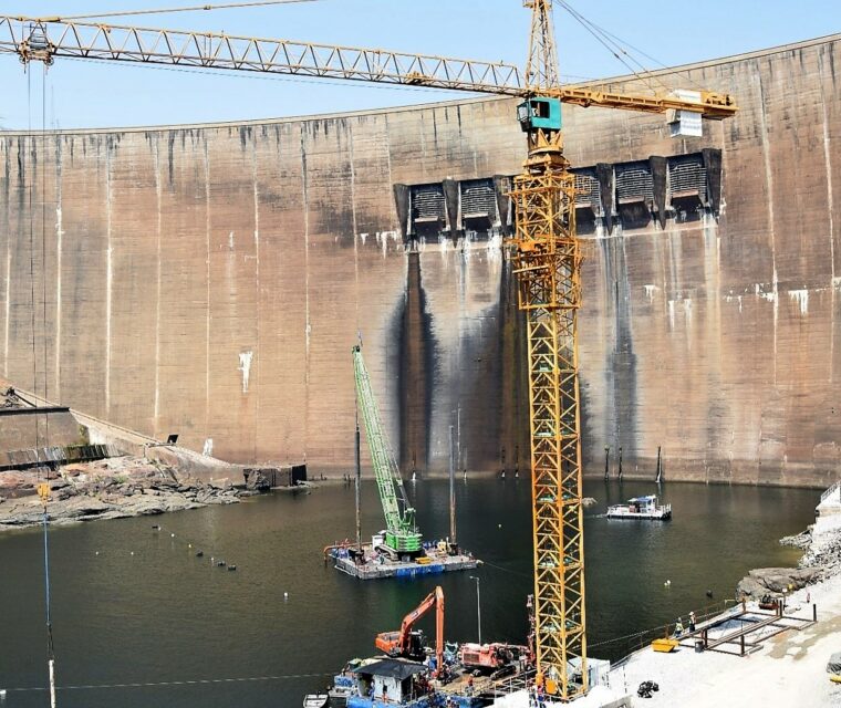
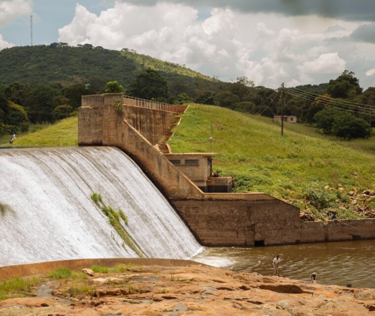
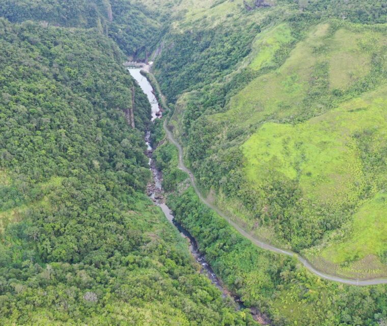
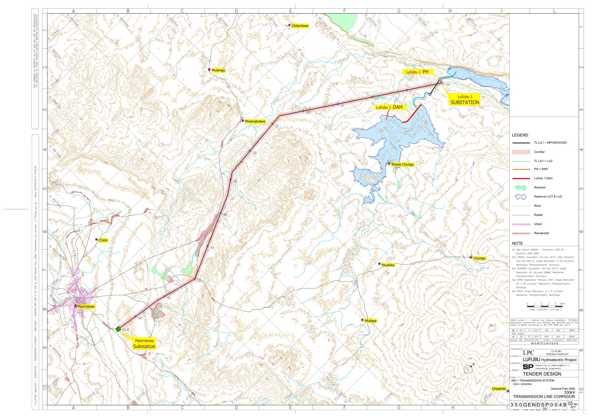
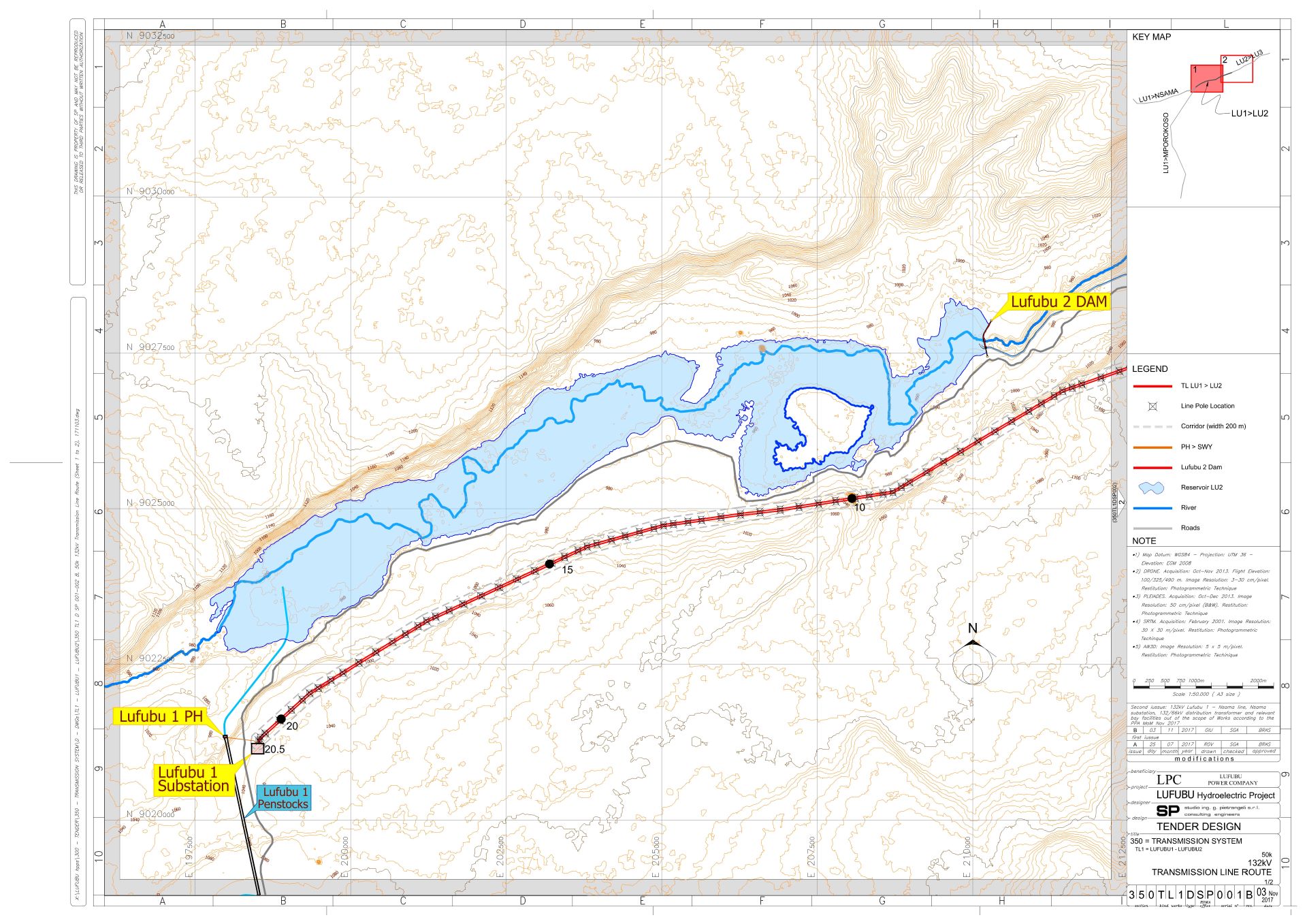
Engineering services for hydropower plants The Lufubu hydropower cascade includes three plants (Lufubu 1, 2 and 3) which exploit an overall hydraulic head of approximately 315 m developing an installed power of 163 MW, in the first stage, which might be increased in a second stage up to 326 MW. Lufubu Cascade was created through the synergy of a visionary Zambian entrepreneur and the engineering imagination of SP. The first Independent Power Producer in Zambia asked SP to study the entire Lufubu River in order to identify potentially promising sites for hydropower exploitation. The entrepreneur chose this area, the least developed in the entire country, given his close sentimental ties to his ancestral birthplace. This adventure led us to the identification of three sites, the design of the plants and the environmental and social impact study of the plants and respective transmission lines. Lufubu 1 hpp includes a bituminous face rockfill dam (BFRD), 60 m high, which will create a reservoir with a total storage of 720 Mm3. The spillway structure is located on a saddle on the left side of the dam and will be controlled by three radial gates which will discharge Q = 5’170 m3/s (PMF). The waterway is formed by a headrace canal, 4.4 km long, and a penstock about 2.6 km long which conveys the flows to the turbines. A surface powerhouse will host a francis turbine with an installed capacity of 66 MW. A second turbine might be installed in a second stage. Lufubu 2 hpp includes a concrete gravity dam, 21 m high, which creates a reservoir with a total capacity of 85 Mm3. The spillway structure is located in the central part of the dam, controlled by three radial gates, and will discharge a Q = 2’250 m3/s corresponding to a flood with a return period of 10’000 years. The waterway is similar to that of Lufubu 1, having however an open canal 6.2 km long and a 670 m long penstock which conveys the flows to the turbines. The installed power will be 44 MW and might be increased in a second stage. Lufubu 3 is the last plant of the Lufubu cascade. A bituminous face rockfill dam (BFRD), 40 m high, will create a reservoir with a total storage of 400 Mm3. A concrete structure in the dam body will be the spillway, controlled by radial gates and discharging up to 5’170 m3/s (PMF). Similarly to Lufubu 1 and 2, the waterway will consists of an open canal 7.8 km long and a 2.1 km long penstock. The Powerhouse will host a Francis turbine with an installed power of 53 MW, that might be increased in the second phase. The Lufubu Cascade is connected to the national grid by a 330 kV transmission line, which departs from the substation of Lufubu 1 HPP and terminates at the Mporokoso. The total length of the route is approximately 63 km. The Mporokoso substation hosts 330kV bays for line departures to Kasama, Lufubu and Kalungwishi stations, as well as two 330/66kV distribution transformer bays for stepping down the voltage for the connection to the distribution grid. The three power stations (Lufubu 1, Lufubu 2, Lufubu 3) are linked to each other by 132kV overhead lines, single circuit, for a total route length of approx. 43 km. The corridor of the lines from Lufubu 3 – Lufubu 1 connects the Lufubu 3 HPP, located at about 1 km from Kabulwe village to Lufubu 2 HPP from here, another corridor develops up to Lufubu 1 HPP, along the Lufubu River. Each power plant of the Lufubu cascade is provided with an outdoor air insulated switchyard. The generating unit of each power plant is coupled to a 132/11kV step-up transformer, rated respectively 80MVA (LU1), 50MVA (LU2) and 63MVA (LU3). Lufubu 1 substation is then interconnected to the 330kV grid via two 200MVA 330/132kV autotransformers (ATRs). PLACE CLIENT YEAR LUFUBU 2 ( IP = 86 MW ) LUFUBU 3 ( IP = 106 MW ) NSAMA Zambia
Lufubu Hydropower Cascade
Zambia
Lufubu Hydropower Cascade
Northern Province - Zambia
LPC Lufubu Power Company Ltd.
2013 – in progress
Main Features
LUFUBU 1 ( IP = 132 MW )
Zambia
Lufubu Hydropower Cascade
Engineering
ServicesFeasibility study
Detailed Design
Network static and transient Stability Analysis
Environmental and Social Impact Assessment
Technical Advisor for IPP
Tender documents and assistance to the Client for construction bid
Supervision of construction


