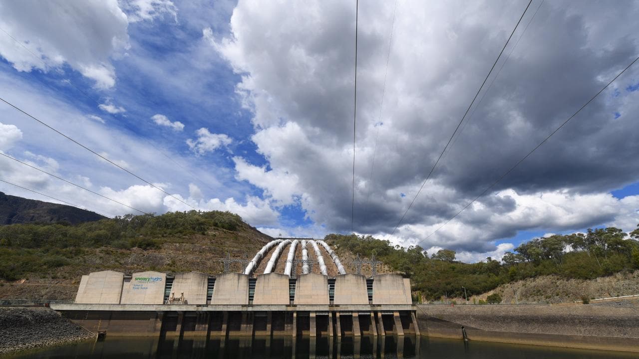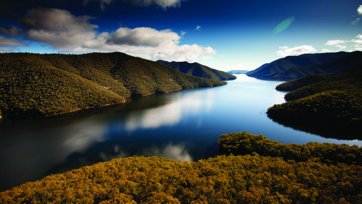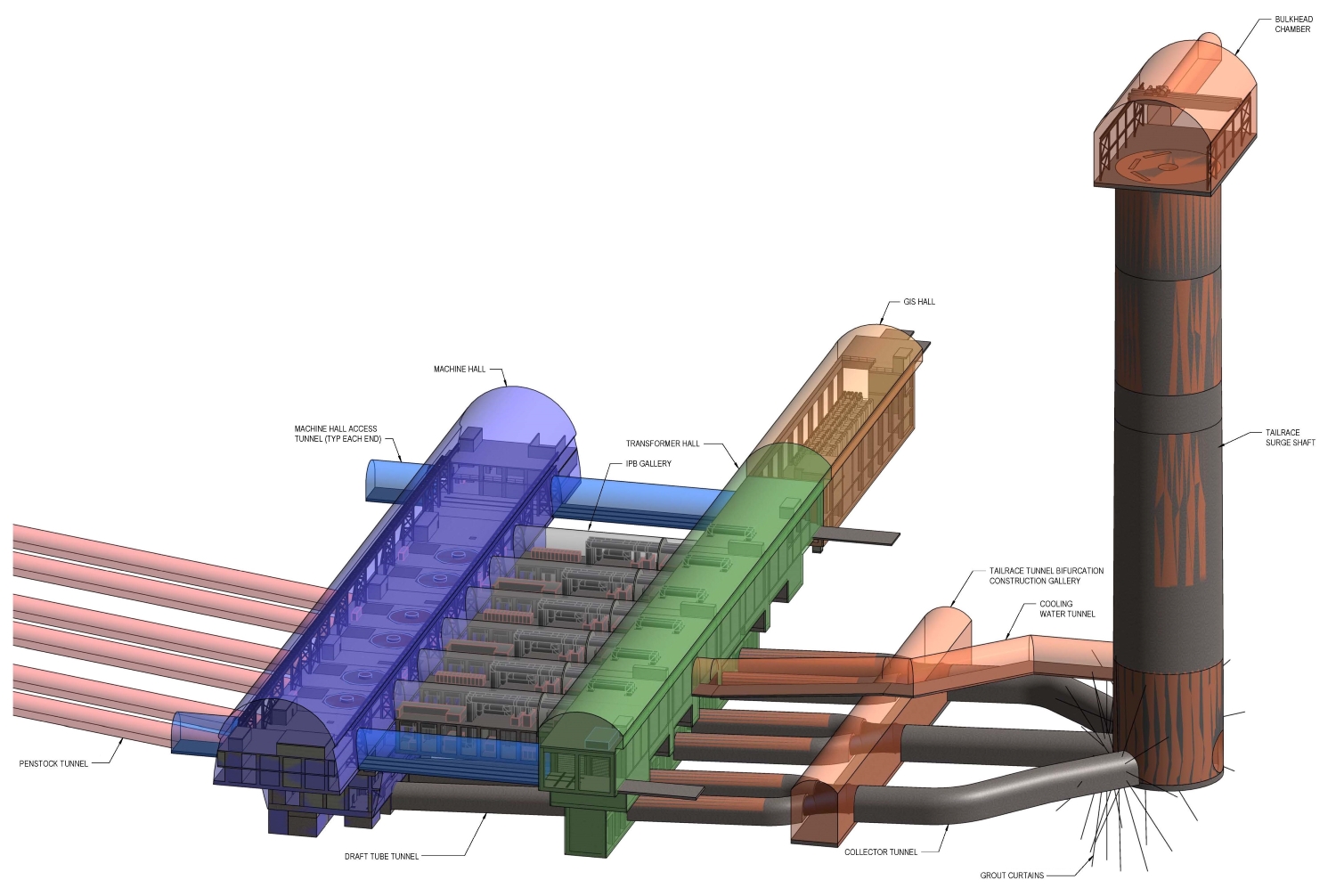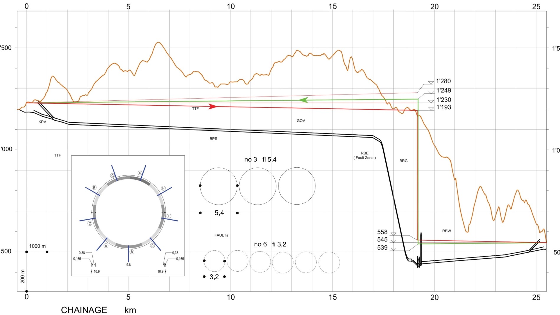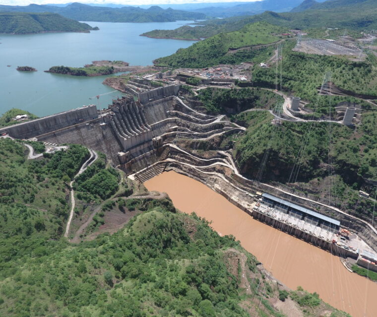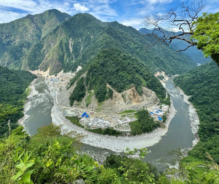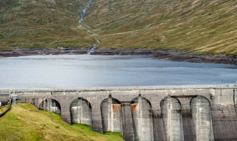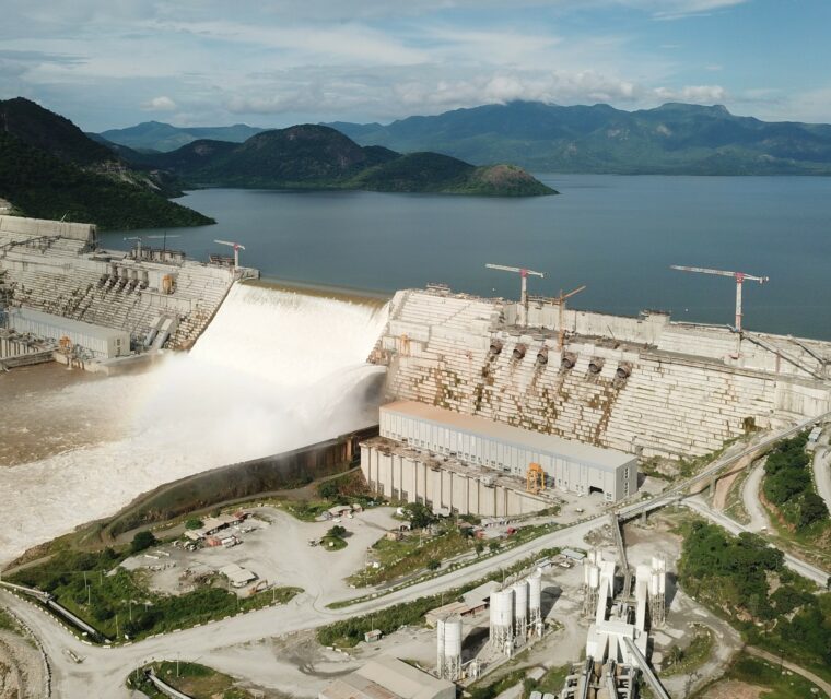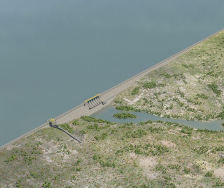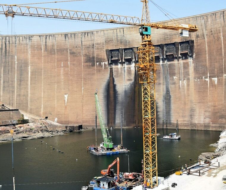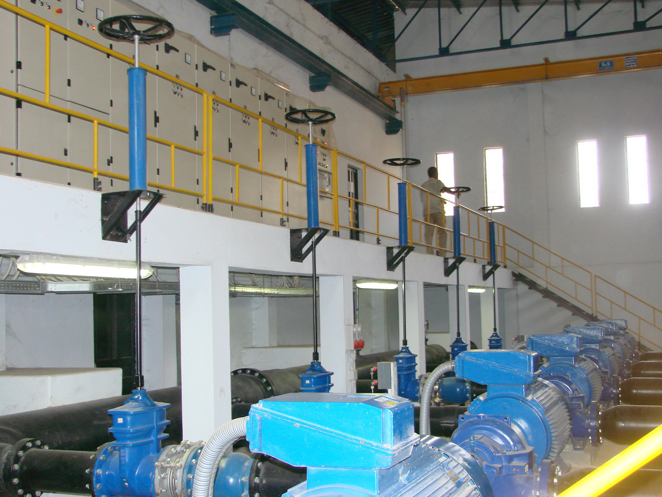
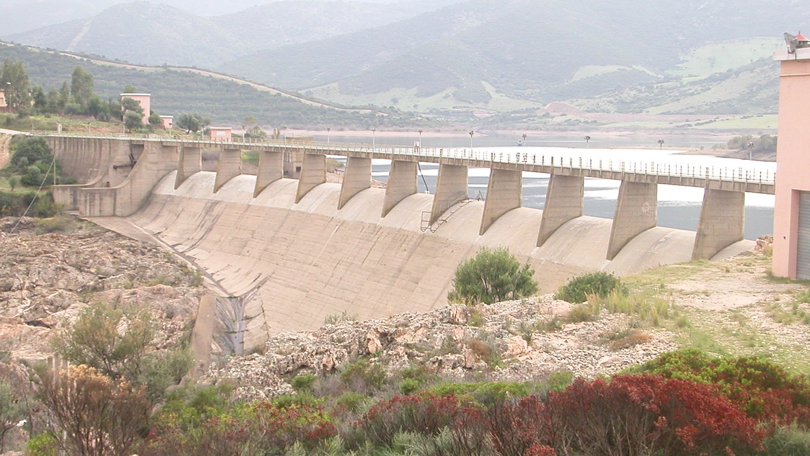
Engineering for pumped hydro plant The project is a pumped hydro plant in Australia providing up 2,000 MW with approximately 350,000 MW/h of energy storage. The project will deliver one of the largest pumped hydro schemes in the world, and will underscore the importance of the Snowy Mountains Scheme’s role in the National Electricity Market: located in the Kosciusciko National Park (KNP) in southern New South Wales, not far from Sidney, this largest renewable energy project will lead the Australia’s transition to a low carbon emissions future. The precious environment of the Snowy 2 Mountains National Park, the size of the Plant and the extreme conditions of water and ground pressures (combined with faults zones) along the waterways make the design of Snowy 2 unique and extremely challenging. The Snowy 2 Plant involves linking two existing dam plants, Tantangara and Talbingo, through an about 25 km of concrete-lined underground tunnel. Intakes/outlets structures will be built at both reservoirs and have been studied to minimize the visual impact on the lake shores. The hydraulic scheme is as follows: a Head Race Tunnel (starting from the upper reservoir), an inclined pressure tunnel (to connect HRT to PH), ending with steel-lined penstocks, and the Tail Race Tunnel (ending in the lower reservoir). This scheme is completed by two surge shafts for both tunnels designed to reduce hydraulic internal pressure. In addition to wet tunnels the project includes dry access and connection tunnels, as the Main Access Tunnel to the power house and its Emergency Cable Ventilation Tunnel. The tunnels will be excavated in drill and blast (D&B) only for very limited initial sections and then by a shielded Tunnel Boring Machine (TBM) with an “universal ring” composed of 9 segments. This construction methodology has the benefits of speed, safety during construction and lower environmental impact. The Power house will be located almost one kilometre underground: when the energy demand is high, the water will be released from the higher reservoir, Tantangara. On the contrary, when the demand for energy is low, the water will be pumped from the lower reservoir, Talbingo, to the higher one. This configuration will provide flexible power, by recycling and reusing the water in a closed loop, and maximise the efficiency of available renewables, by using excess solar and wind energy at times of low demand. PLACE CLIENT YEAR Australia
Snowy 2 Pumped Hydro Electric Scheme
Australia
Snowy 2 Pumped Hydro Electric Scheme
New South Wales - Australia
Future Generation Joint Venture Webuild S.p.A.
2019 – in progress
Main Features
Australia
Snowy 2 Pumped Hydro Electric Scheme
Engineering
ServicesDue Diligence/Review of the Existing Tender Design
Design optimization recommendations for upgraded Preliminary Design
Basis of design
Waterways transient analysis and relevant hydraulic scheme optimization and alternative layout studies and design.